 Mohammad Taha
Smart Irrigation System
IoT irrigation controller — ESP8266 + Blynk
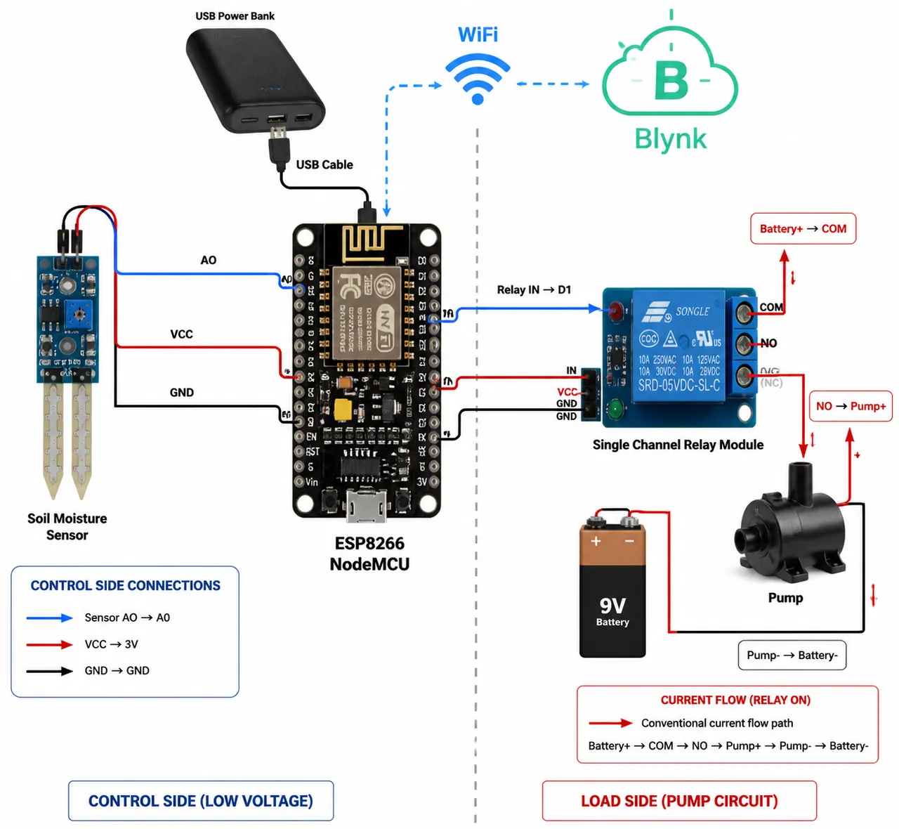
An ESP8266 NodeMCU reads a soil-moisture sensor every second, waters through a relay-driven pump when the soil is dry, and reports to a Blynk dashboard where the pump can also be switched by hand. The watering logic is a small non-blocking state machine.
- Built with
- C++ (Arduino)ESP8266 NodeMCUBlynk IoT
- Type
- Personal project
- Source
- Public on GitHub
How it decides
Soil reading → pump decision
- person
- guesses / untrusted
- decides
- process
- storage
- third party
- trust boundary
Boundary Where guessing stops and something deterministic decides.
- Dry (> 800) → pump on for 3 s → ignore readings for 40 s → act again. code
- Non-blocking: millis() comparisons, no delay(). code
- Relay pin is driven HIGH at boot so the pump starts off. code
The drawing, in words
Smart Irrigation System: Soil reading → pump decision. Left of the redline is “Sensor & remote input”; right of it is “Firmware decides”.
- Soil sensor — analog A0 (Sensor & remote input)
- Blynk app — manual switch (Sensor & remote input)
- Blynk cloud — V0 V1 · V2 (Sensor & remote input)
- Threshold — > 800 means dry (Firmware decides)
- Override — BLYNK_WRITE(V2) (Firmware decides)
- State machine — pump 3 s · wait 40 s (Firmware decides)
- Relay — active-LOW · D1 (Firmware decides)
- Pump — mini DC pump (Firmware decides)
Connections
- Soil sensor → Threshold (every 1 s)
- Blynk app → Blynk cloud
- Blynk cloud → Override (V2)
- Threshold → State machine
- State machine → Relay
- Override → Relay (on until off)
- Relay → Pump
More screens
What was built
- Circuit with an ESP8266 NodeMCU (ESP-12E), soil-moisture sensor, single-channel relay and mini DC pump. repo docs
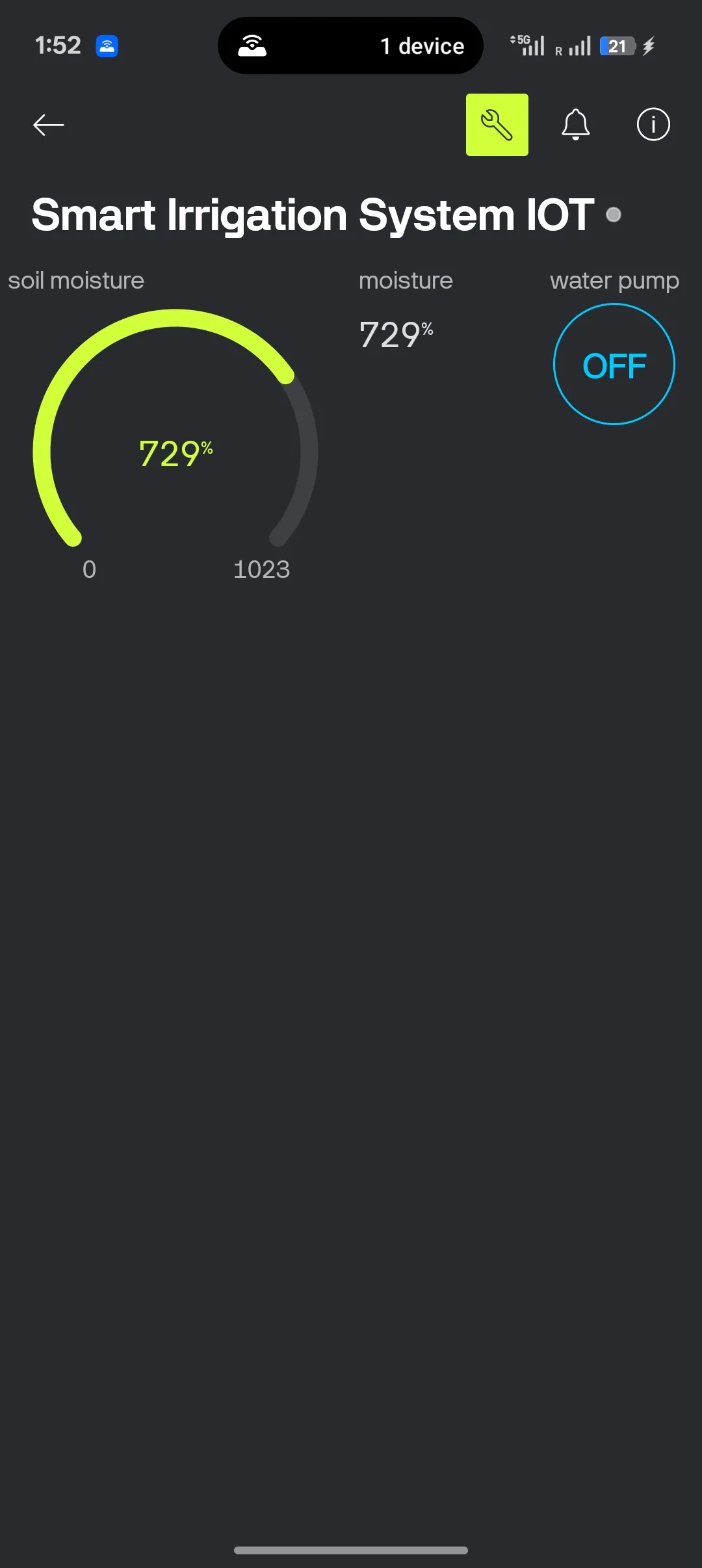
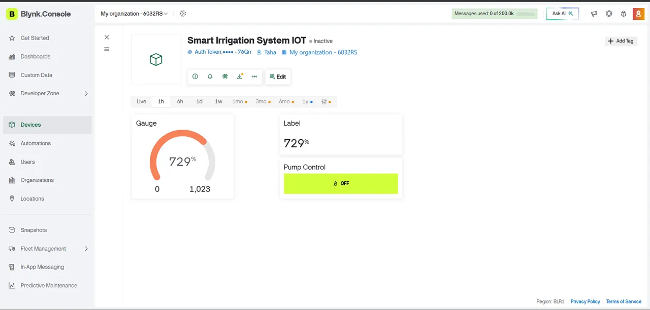
- Firmware that pushes moisture to Blynk virtual pins V0/V1 and listens for a manual switch on V2. code
My part
- Built solo: circuit, firmware and Blynk dashboard.
Limits and open work
- The README wiring table lists D2 for the relay while the firmware drives D1 — the docs drifted from the code. code
- Runs on batteries and a power bank; solar power and a tank-level sensor are listed as next steps. repo docs
Decisions worth knowing
Water, then wait
A reading above 800 means dry. The pump runs for 3 s; then for 40 s the firmware keeps reading and reporting but won't act, giving the water time to soak in. One dry reading can't flood the pot.
code
Never block the radio
Timing uses millis() comparisons instead of delay(), so Wi-Fi and Blynk keep running while the pump is on.
code
Start safe
The relay is active-LOW, so the pin is driven HIGH at boot and the pump starts off.
code